


 Fax:13099600376
Address:Maiwei Science Tech Park Qingmeng Quanzhou Fujian China
E-mail:maiwei@maiwei.com.cn
TDD-LTE Wide Band Pico Repeater (Intelligent)
TDD-LTE Wide Band Pico Repeater (Intelligent)
MN-L1800-XX-XX-XXI
MN-L2300-XX-XX-XXI
MN-L2600-XX-XX-XXI
Features:
■ Designedwith low noise figure, great out-of-band rejection ability.
■Intelligent ALC technology and attenuation regulation, Gainfunction supports automatic detection, automatic test input signal power,automatic tracking for uplink gain Settings.
■ Highlinearity PA, maximum 70dB gain.
■ Lowpower consumption, compact size, easy for maintenance and installation.
■Automatic detection of transmitting antenna and receivingantenna isolation ratio, automatic control gain, self-excited protectionfunction, to solve the instability of base station interference equipment.
■ Allparameters can be adjusted automatically, automatic monitoring and processing.
■Uplink and Downlink time slot than adaptive function. Automaticsearch area has time slot than configuration, automatic configuration softwareto realize synchronous inside.
■ AluminumCabinet (IP30).
Product Description:
MN-XXXX-XX-XX-XX is a cost-effective solution for wireless enhancement.Repeater receives donor signal from air via donor antenna, after signalamplification, signal will transmit to target service areas. All parameters canbe adjusted automatically, automatic monitoring and automatic processing.
Electrical Specifications:
Items | Specifications | ||||
Reverse | Forward | ||||
Work Frequency Range (MHz) | LTE1800-F ,optional | MODEL1 | 1880-1920 | ||
LTE2300-A,optional | MODEL2 | 2320-2370 | |||
LTE2600-D,optional | MODEL3 | 2570-2620 | |||
Operating Bandwidth (MHz) | wide band | ||||
Max. Output Power (dBm) (Center frequency) | 10~20±2,optional | 10~20±2,optional | |||
Max. Gain (dB) (Center frequency) | 70±3 | 70±3 | |||
ALC(dB) | ≥20 | ≥20 | |||
AGC (dB) | ≤|±2.0| | ≤|±2.0| | |||
AGC Range (dB) | 0 ~ 20 | 0 ~ 20 | |||
Noise Figure (dB) (Max. gain) | ≤6.0 | ≤6.0 | |||
Ripple In Band (dB)at 25℃ | ≤6.0 | ≤6.0 | |||
VSWR(Power up, Max Gain, Pin=-45dBm) | ≤1.8 | ≤1.8 | |||
Time Delay (us) | ≤1.5 | ≤1.5 | |||
Out of band Spurious Emission (dBm) | 9KHz~150KHz | ≤-36/1KHz | ≤-36/1KHz | ||
150KHz~30MHz | ≤-36/10KHz | ≤-36/10KHz | |||
30MHz~1GHz | ≤-36/100KHz | ≤-36/100KHz | |||
1GHz~12.75GHz | ≤-30/1MHz | ≤-30/1MHz | |||
3rd Inter-modulation attenuation (dBc) (Max Gain) | ≤-36/30KHz | ≤-36/30KHz | |||
Spectrum Emission Mask (Max. Gain)@TDD-LTE | 0.05£ f_offset < 5.05MHz | -7~-14/100KHz | |||
5.05 £ f_offset < 10.05MHz | -14 dBm /100KHz | ||||
10.5 £ f_offset <f_offset max | -15 dBm /1MHz | ||||
EVM(%)RMS | 64QAM | ≤8 % | ≤8 % | ||
Frequency error | ≤0.05PPM | ≤0.05PPM | |||
Switching time Mask(us) | OFF to ON | ≤17 | ≤17 | ||
ON to OFF | ≤17 | ≤17 | |||
Synchronous range | ≥30dB | ||||
Synchronization scheme | Level synchronization | ||||
Donor downlink signal power(dBm) | RSRP≥-80dBm | ||||
Mechanical Specifications:
Items | Specifications |
Impedance (Ω) | 50 |
Radio Connector | SMA(f) |
Power Supply | AC100~240V, 50Hz |
Weight (Kg) | ≤1.0 |
Power Consumption (W) | ≤25 |
Dimension (mm) | 157×127×21 |
Enclosure Protection Degree | IP30(indoor) |
Operating Temperature (℃) | -5~ +45 |
Humidity (%) | 95 |
Control Function | Intelligent, internal automatic control |
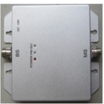
Indicate Specifications:
synchronizing indicator(SY) | Green light | synchronization |
Green flashing | Not synchronized | |
light not bright | Equipment power failure or no electricity | |
Isolation indicator lamp(ISO) | Green light | Isolation is good |
Green flashing | Isolation is not good | |
Red&green flashing | Isolation is Poor | |
Red flashing | Isolation is very poor | |
Red light | isolation is Super poor | |
light not bright | Isolation is too small, into the device protection status | |
Downlink output power indicator(PM) | Green light | Pout is Poutmax±2dBm |
Green flashing | Pout=(Pmax-2~Pmax-5)±2 dBm | |
Red&green flashing | Pout=(Pmax-6~Pmax-9)±2 dBm | |
Red flashing | Pout=(Pmax-10~Pmax-13)±2 dBm | |
Red light | Pout≤(Pmax-14dBm)±2dBm | |
light not bright | DL input is too large, access to equipment protection | |
Three lights flashing at the same time | This condition is automatically detected and adjusted after the device has been added to the device, and the 10s is completed. | |
protection function | When the module of the downlink input signal, beyond the control range of the module, turn off the link, in the next 15 seconds after the start of the three restart, if the input state is still not changed, then shut down, 24 hours after the resumption of testing. | |
Note1: the need to ensure that the "SY" & "ISO" indicator for "green light". Note2: Gpmax is Nominal gain, Pmax is Nominal output power | ||